
Screen-Off Integration Trend
Bolt-On Screens Are Disappearing; the Material Itself Becomes the Interface
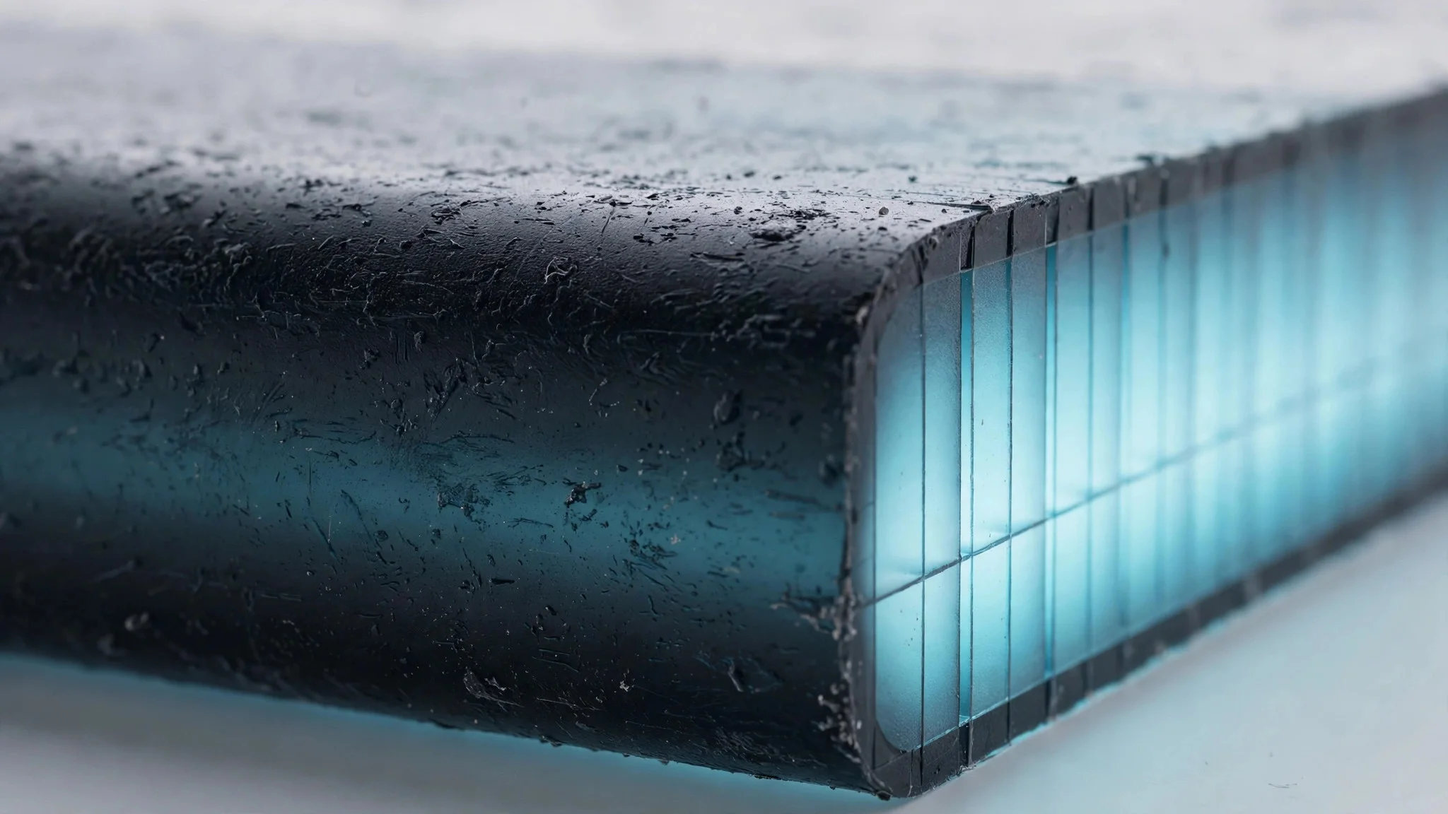
In late 2026, STARLUX Airlines' A350 flagship cabin debuted Collins Aerospace's Secant illuminated panels: unactivated, they are seamless matte decorative surfaces; once awakened, high-CRI ambient light, dynamic flight paths, and brand light effects emerge from beneath the material texture.
Consumer electronics, smart cockpits, medical instruments, and premium appliances are abandoning obtrusive black screens for 'invisible when off, interactive when on' smart surfaces — but a shimmer of light on a rendering meets ghost images, light leakage, and sink marks the moment it enters the injection-molding shop.
Mold-Forming Iron Rules
Uniform Walls and Preload: Lock Optical Problems Inside the Mold
A 0.05 mm shrinkage depression invisible on a conventional housing becomes lens distortion on a hidden-until-lit surface; so fixed light-guide posts cannot use snap-fit studs directly on the back — rib thickness and stud-root glue reduction must be fixed at the CAD stage.
With full closed-loop 3D tolerance stack-up analysis and floating clips releasing thermal stress, assembly gaps and light-leak channels can be computed before production, rather than discovered through trial-mold rework.

Getting the Product Right
Flawless When Off, Crisp When Lit — That Is What Passing Production Means
The smart-surface race is not won on renderings, but on whether transmittance windows, light-blocking structures, and uniform walls were computed at the drawing stage; done right, the material can be both invisible and expressive.
FAQ
FAQs on Hidden-Until-Lit Surfaces
Four questions most often asked about transmittance, ghost images, AI mold-making, and production delivery.
What are the core processes and engineering challenges of hidden-until-lit surfaces?
Technology that looks like a continuous matte native-material surface when inactive and shows a clear interface when lit. Three challenges: transmittance too high reveals circuit boards, too low dims the light; total internal reflection inside semi-transparent substrates causes adjacent icons to bleed light; micro-depressions from cooling back ribs become dark spots under backlight.
Why do semi-transparent plastics reveal internal PCB 'ghost images' in strong light, and how is it solved?
Ambient light penetrates the semi-transparent plastic and mirrors off reflective internal components. The answer: optical-grade PC with nano diffusion particles, total transmittance held at 5%–12%, micron-level low-gloss etching on the outer surface to scatter strong light, and matte black paint on internal components to absorb stray light.
Why can't AI-rendered smart illuminated surfaces go straight to mold-making?
AI outputs pixels or polygon meshes without parting surfaces, 1°–2° draft angles, or wall-thickness uniformity control; it cannot read LED beam angles, light paths, or grid preload, and cannot produce 2D GD&T drawings with tolerance annotations. Production requires engineering teams to rebuild parametric CAD solids.
How does IDING guarantee zero rework for opto-mechatronic hardware molds?
By following the full engineering white-box discipline: delivering 3D STEP parametric solids with complete feature trees, running mold-flow simulation before finalizing to optimize gate and weld-line positions, performing 3D assembly tolerance stack-up analysis, and issuing 2D manufacturing drawings with strict geometric tolerances — mold shops cut directly with no second revision.
Can't Achieve Screen-Off Texture? Start by Computing It at the Drawing Stage
Struggling with uneven light transmission, icon light leakage, or trial-production rework? IDING DESIGN can move optical and tolerance problems upstream to the drawing stage — 19 years of industrial design and engineering delivery experience, solving them before they happen.